5. Terms for connections and electronic characteristics
After having looked at a few mechanical aspects of potentiometers, let's return to the electronic features.
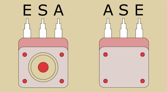
Since it may make a difference how a three-phase potentiometer is connected to a circuit, the three terminals are commonly given different designations for clarity's sake. The following table shows three possibilities
| input | wiper | output |
| A | S | E |
| 1 | 2 | 3 |
| c | b | a |
From the operating perspective, the output solder tail (E) is to the left, the wiper solder tail (S) in the middle and the input solder (A) tail is to the right.

The connections of a potentiometer from top to bottom
Characteristic impedance, tolerance and linearity
Regarding electric features, the so-called characteristic impedance is a potentiometer's most important parameter. Comparing the range available, it is apparent that the choice is quite a bit more limited than with fixed resistors. Within a decade (a ratio of 1:10) there are usually only a very few values available. Depending on the manufacturer, you'll find two different series. With the American manufacturer CTS and others, this series is usually 1, 2.5, and 5, as well as values which are multiplied with the respective power of ten; for example 100kOhm, 250kOhm, and 500kOhm. But most manufacturers stick to the E-series as specified in the DIN Standard IEC 60063. The E3 series frequently used for potentiometers then includes the values 1, 2.2 and 4.7.
A resistor's tolerance describes the maximum allowable deviation from the characteristic impedance indicated. Thus, a resistor of 100kOhm with a tolerance of 10% may range from 90kOhm to 110kOhm in operation. For potentiometers, a tolerance of 30% or even greater has become standard. Therefore, you will frequently only find three values per decade. Within the allowed tolerances, these then theoretically cover all values within the decade due to unavoidable variation in production.
Manufacturers also supply potentiometers in accordance with the E6 series and with narrower tolerance on request. However, these pots are not specially made but rather selected from a large quantity by measuring them for specifications, since the specialised production of narrow-tolerance pots would be very complex and thus expensive.
The so-called linearity is a further mark of a potentiometer's quality, and it describes the maximum allowed deviation of the actual from the theoretical resistance curve. Depending on the characteristic impedance, the tolerance may range from 4% to 6%. In practice, you should go for a potentiometer with as low a linearity tolerance value as possible.


